Shaping the Future of Clean Energy
Vertical Axis Wind Turbine -- VAWT


Vertical Axis Wind Turbine (VAWT) — VC-Ready Investment Pitch Deck - 1
Canada’s Flagship Net‑Zero Infrastructure Project
Status: Patent Pending — Canadian application filed
1. Executive Summary
We are building a 1‑MW modular VAWT platform for low‑wind, turbulent, and extreme sites where HAWTs underperform. Each MW avoids ~2,100 tCO₂e/year and displaces ~900,000 liters of diesel, with an estimated ~$210k/MW‑yr carbon floor revenue via CfD, stacked with electricity sales. The architecture combines a non‑contact bearing and a hybrid auxiliary drive to start at 1.5–3 m/s, with ground‑level O&M and yaw‑free operation. We seek pre‑seed funding to deliver a prototype, a 1‑MW demonstration site, and certification milestones over 18 months.
Key Facts:
Cut‑in wind (start) 1.5–3 m/s (hybrid‑assisted)
Per‑MW impact /year ~2,100 tCO₂e avoided; ~900k L diesel isplaced
2. Problem & Opportunity
Problem — Diesel lock-in at hard sites.
Remote northern communities, islands, mining/industrial sites and ports still run on diesel: expensive, noisy and high-emission (~2.7 kg CO₂ per liter). Conventional HAWTs underperform in low wind (<3 m/s), rapidly shifting wind directions and complex terrain (cliffs, ports, urban turbulence). Result: stranded wind resources, unstable power costs and stalled decarbonization at the edge of the grid.
Opportunity — Purpose-built VAWT unlocks stranded wind.
A low-noise, yaw-free VAWT that starts at 1.5–3 m/s and tolerates turbulence can replace diesel at these sites. Per MW per year, the platform targets ~2,100 tCO₂e avoided and ~900,000 L diesel displaced, stacking carbon CfD floor revenue (~$210k/MW-yr) with power sales, while improving energy security and community acceptance.
3. Solution & Architecture
Our patented non-contact bearing + hybrid auxiliary drive architecture is purpose-built for low-wind, turbulent, and harsh coastal/arctic sites.
Frictionless load support: the non-contact bearing carries rotor loads with minimal wear and no lubricants, extending life and reducing O&M.
Autonomous low-wind start: the hybrid drive enables cut-in at 1.5–3 m/s and fast restart after storm safe-stops.
Yaw-free, 360° wind acceptance: no active yaw system; lower mechanical complexity and higher availability in shifting winds.
Ground-level O&M: service is performed on the ground, reducing downtime and crane dependence.
Modular deployment: 1-MW units are helicopter/crane-deployable on cliffs, islands, or platforms and engineered for −50 °C operation with rapid de-icing.
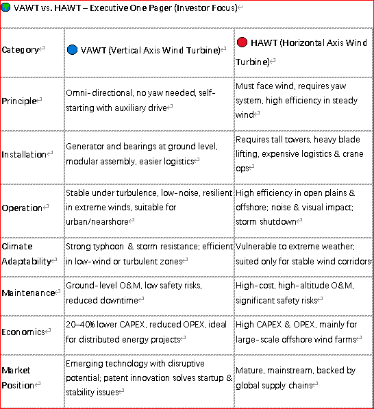
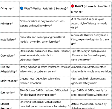
4. Technical Advantages (VAWT vs HAWT) — Quantified (illustrative; site-dependent)
Why it wins at the edge: fewer moving parts up-tower, starts in lower wind, behaves nicely in turbulence, and keeps the community happy on noise.
Community noise: VAWT < ~40 dB(A) @ 200 m (target) vs HAWT > 50 dB(A) → easier siting & permits.
Yaw / gear train: VAWT yaw-free + direct-drive-ready (no active yaw system; lower part count) vs HAWT active yaw + gearbox/pitch → fewer failure modes, higher availability.
Annual maintenance hours: ↓ ~50–70% vs HAWT via ground-level O&M (less crane time, faster turns).
Low-wind / turbulence: Cut-in 1.5–3 m/s (assisted); tolerant of shifting inflow vs HAWT efficiency drop & fatigue hotspots in complex terrain.
-- Continue to Pitch Deck-2
Vertical Axis Wind Turbine (VAWT) — VC-Ready Investment Pitch Deck - 2
--To be Continued
5. Markets — TAM / SAM / SOM
• TAM: diesel‑reliant and wind‑rich remote/island/industrial/port sites globally.
• SAM: Canada + Nordics + selected MENA coastal & island markets with wind resources and policy support.
• SOM (18–36 m): first wave of 1–3 MW sites via community partners, port authorities, and industrial microgrids.
Priority use cases: northern/Indigenous communities, coal retirement replacement, gas‑peaking microgrids, islands/ports, urban distributed microgrids.
6. Business Model & Unit Economics
Revenue stack: Carbon CfD floor (~$100/tCO₂e → ~$210k/MW‑yr) + electricity sales (PPA or merchant). Per‑MW impact: ~2,100 tCO₂e avoided & ~900k L diesel displaced; ≥300 households powered (site‑dependent).
7. Implementation Plan & Milestones (0–36 months)
Phase 1 (0–12 m): design, prototype fabrication, wind‑tunnel & controls validation.
Phase 2 (12–24 m): 1‑MW demonstration site, grid tie‑in, commissioning, MRV report.
Phase 3 (24–36 m): production ramp, multi‑site deployment, export readiness.
Acceptance criteria:
• Prototype Ready = wind‑tunnel + control tests passed; subsystem telemetry validated.
• Demo Online = sustained grid‑connected generation + MRV report delivered.
8. Funding Ask & Use of Proceeds (18 months)
Ask: $2.0M SAFE (equity) for 18 months to deliver prototype, 1‑MW demo, and certification milestones.
Equity SAFE (40%) $2.00M
Non-dilutive (45%) $2.25M
In-kind (10%) $0.50M
Contingent SIF (≤5%) $0.25M
Total $5.00M / 18 months
9.Extreme Conditions Ready
Built for coastal & arctic harshness. The platform is engineered for high-gust events, storm-aware safe-stop/restart, and rapid de-icing, enabling siting on cliffs, islands, ports and other complex terrain where conventional turbines struggle.
Design features for harsh sites
Low-temperature operation: rated for −50 °C environments with cold-weather elastomers and heater-assisted enclosures.
Gust & turbulence tolerance: yaw-free architecture with hybrid assist for controlled ride-through and fast restart after storm stops.
De-icing: active thermal + control scheduling for rapid ice shedding and balanced spin-up.
Marine protection: corrosion-resistant coatings (C5-M class approach), stainless fasteners, sealed connectors.
Ingress & lightning: IP-rated electronics, surge suppression and lightning protection per IEC 61400-24 path.
Serviceability in weather windows: ground-level O&M reduces crane dependence and shortens post-storm recovery.
Validation plan (illustrative)
P1: cold-box, salt-fog, and HALT testing on bearing/drive/electronics; turbine-in-tunnel turbulence profiles.
P2 (1-MW demo): storm event telemetry, automated safe-stop/restart logs, de-icing cycle timing, availability vs. wind regime.
FTO/Compliance: IEC 61400-1 design-class pathway with site-specific Class-S assumptions.
Innovation
Leading advancements in engineering and defense.
Contact
Support
+1-800-555-0199
© 2025. All rights reserved.